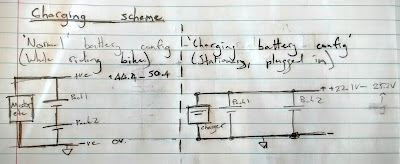
Battery charging circuitry part 1
On the left hand side is the normal configuration of the battery pack when riding the bike. Each one of the battery symbols represents a "pack" of 18 batteries, in 6S3P configuration (a series string of 6 packs, in parallel 3 times). These two packs are connected in series, combining for a total voltage of ~50V. The right hand side shows the charging configuration. Pack one and pack two are now in parallel, effectively halving the required charge voltage to ~25V.
So how to achieve this?
Shown above is my switching scheme, using two single pole, double throw relays (SW1 and SW2). The diagram shows the relays in their "normal" mode, connecting the two packs in series. When energised, the relays will swing to their alternate position, connecting the packs in parallel.
I went ahead and bought a couple of relays from element14.com. I chose Durakool automotive relays (DG85B-8011-76-1012-DR), because can handle the currents and voltages I expect to pump into the motor. After they arrived, I connected them up to a power supply and a scope, and tested the design.
I simulated two battery packs using a dual-channel benchtop power supply at work. This way I could set the current limits really low, just in case I stuffed something up. As can be seen below, this likely happened multiple times.
 |
| The relays connected up with alligator clips. |
Sure enough, the relay circuit appeared to work in principle. The packs were reconfiguring from series to parallel on energising the relays, and reverting back again upon disconnecting the power.
Jared warned me about current spikes across the batteries when disconnecting the relays. These come as a result of the coils in the relays wanting to discharge upon the rapid change in current during disconnection. These spikes could potentially damage the battery packs, so I needed to quantify the effect, in order to determine the scale of protection necessary for mitigation.
I connected a scope across the battery packs, and activated and deactivated the relays. As can be seen, a spike of ~4V is present during the switching, though not for long. This will most likely be dealt with by fitting 25V zener diodes across the packs. More on that, along with the rest of the switching circuit, later.
*This statement is not based on any research/facts. Look, I just wanna play around with relays alright?


Bravo! Excellent crocodile clip technique
ReplyDelete